Found your Raspberry PI Pico in a cupboard that you opened 2 years before… Get along with this project to make a line follower robot using Raspberry Pi Pico and a few other Stuff
What is a Line Follower Robot?
A line follower is a type of autonomous robot that can detect and follow a line drawn on the floor, typically a black line.
Components Required
| Component | Quantity | Notes |
|—-|—-|—-|
| Raspberry Pi Pico | 1 | Use the Pico H for easier pin access |
| BFD-1000 IR sensor array / any 5 array IR sensor Module | 1 | To detect the Black Line |
| L298N motor driver | 1 | To drive motors precisely |
| BO Motors (3–12V) | 2 | Preferably 12V ones 🙂 |
| Bo motor Wheels | 2 | Wheels For Bo Motor |
| Caster wheel (free wheel) | 1 | To balance the front |
| LiPo Battery (12V) | 1 | Or any regulated 12V source |
| Wires, breadboard, etc. | As needed | For connections |
| Computer | 1 | For programming and debugging |
Cooking the Pi🍳
The Software Part
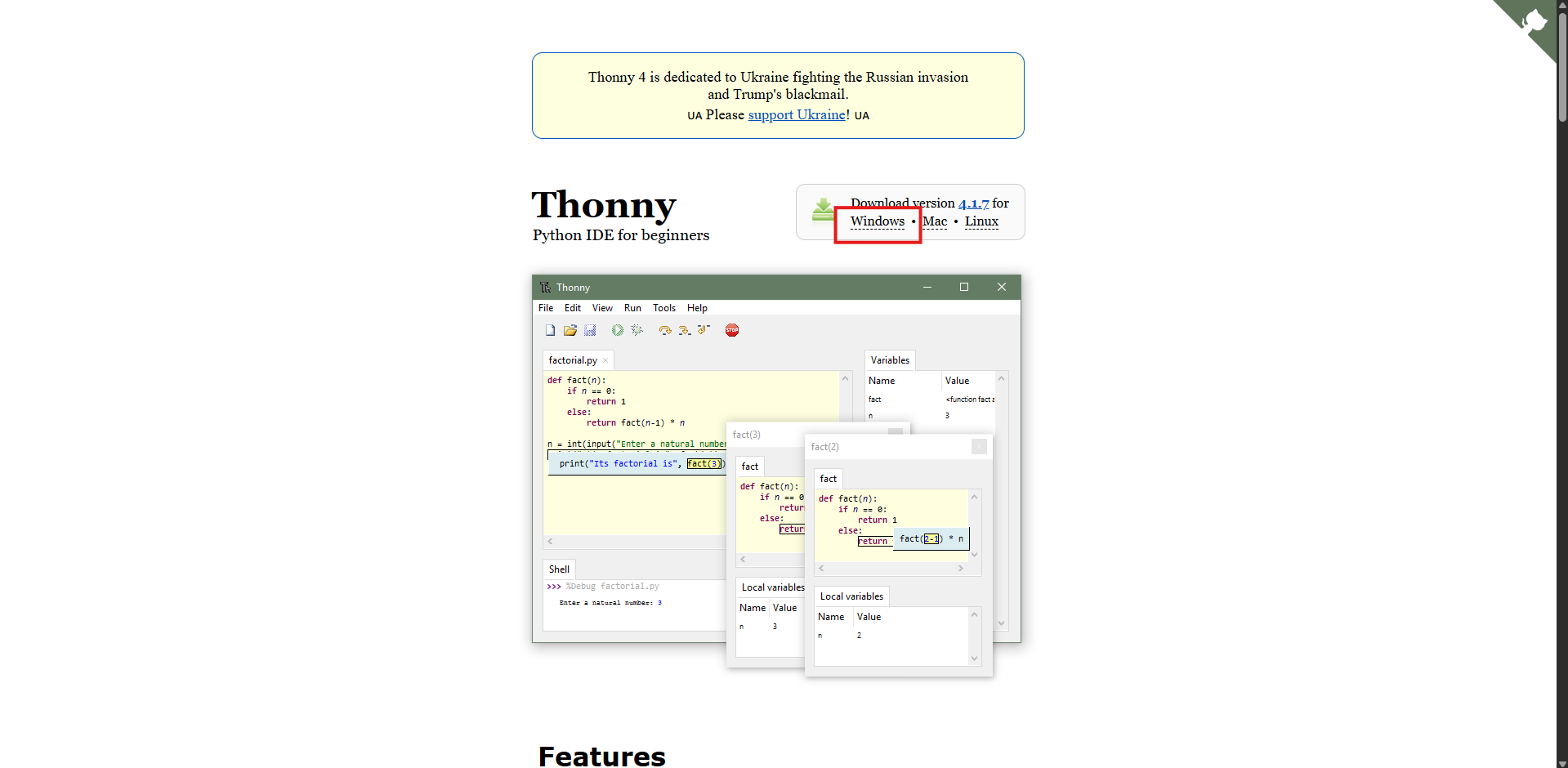
1. Installing Thonny IDE
-
Visit: thonny’s Website
-
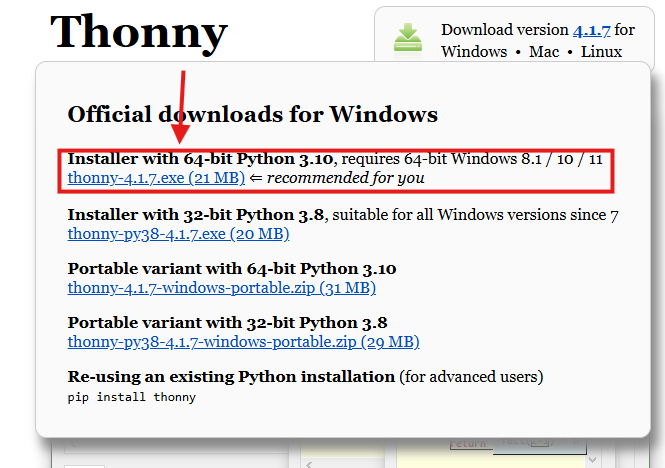
Download it for your OS (Windows/Mac/Linux).
-
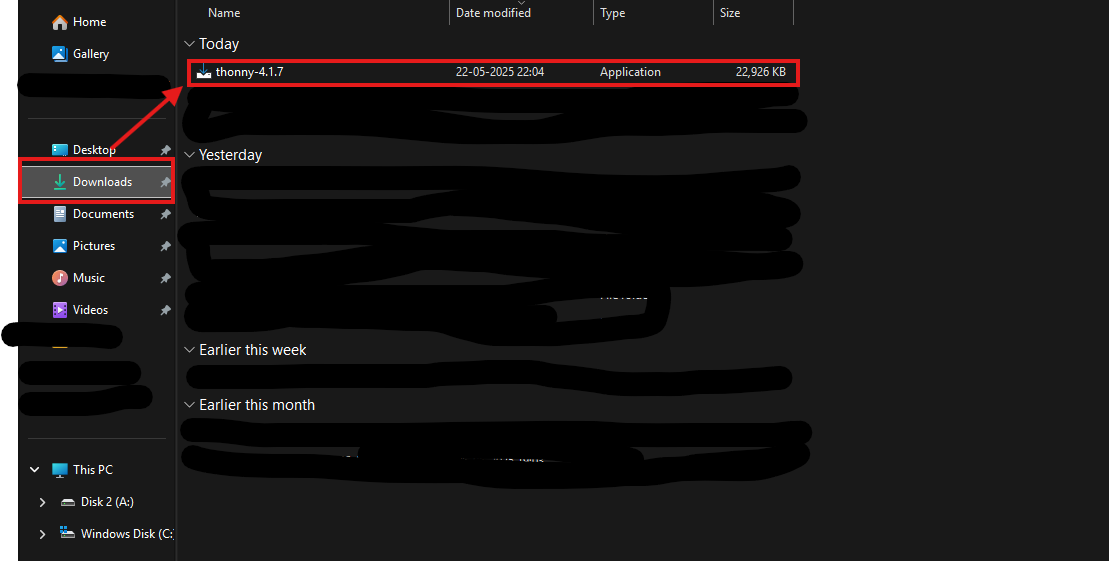
Navigate to the Downloads folder after the .exe file has been downloaded in File Explorer
-
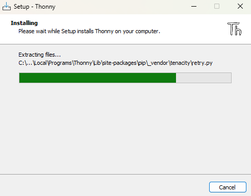
Then click on the .exe file (thonny-4.1.7.exe) to execute the application and click on next until you see that the thonny is being installed
Flashing the pico with Micropython Firmware
:::info
If you have already flashed the micropython firmware the you can skip to next part
:::
Plug in your Pico while holding the BOOTSEL button.
- It appears as a USB drive.
- Go to micropython.
uf2[ file]() download for Pico - Download
.uf2the file and copy it to the Pico USB drive. - Pico will reboot into MicroPython.
Set up Thonny
-
Open Thonny
-
Go to Run > Select Interpreter > MicroPython (Raspberry Pi Pico)
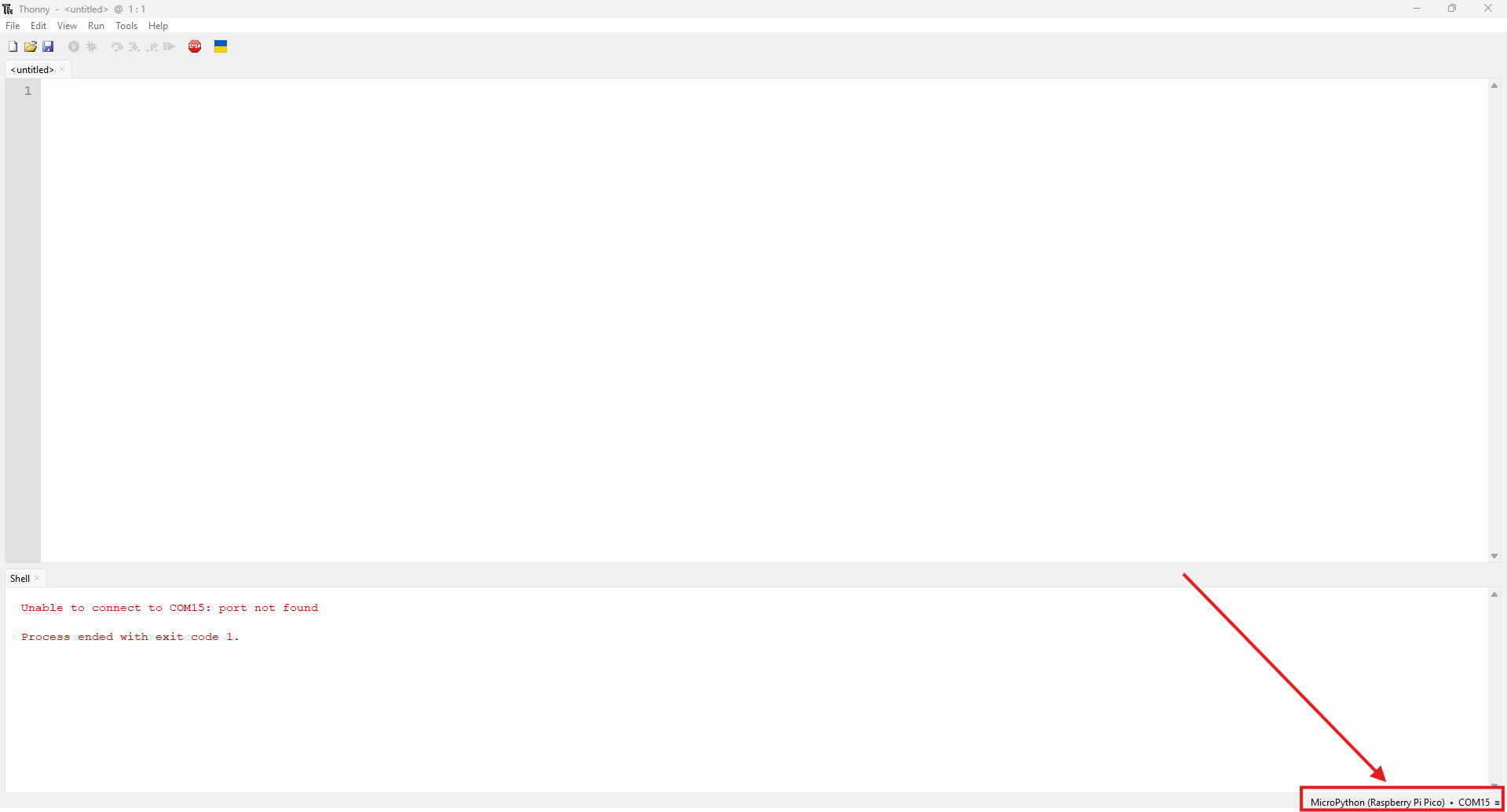
-
Select the right port.
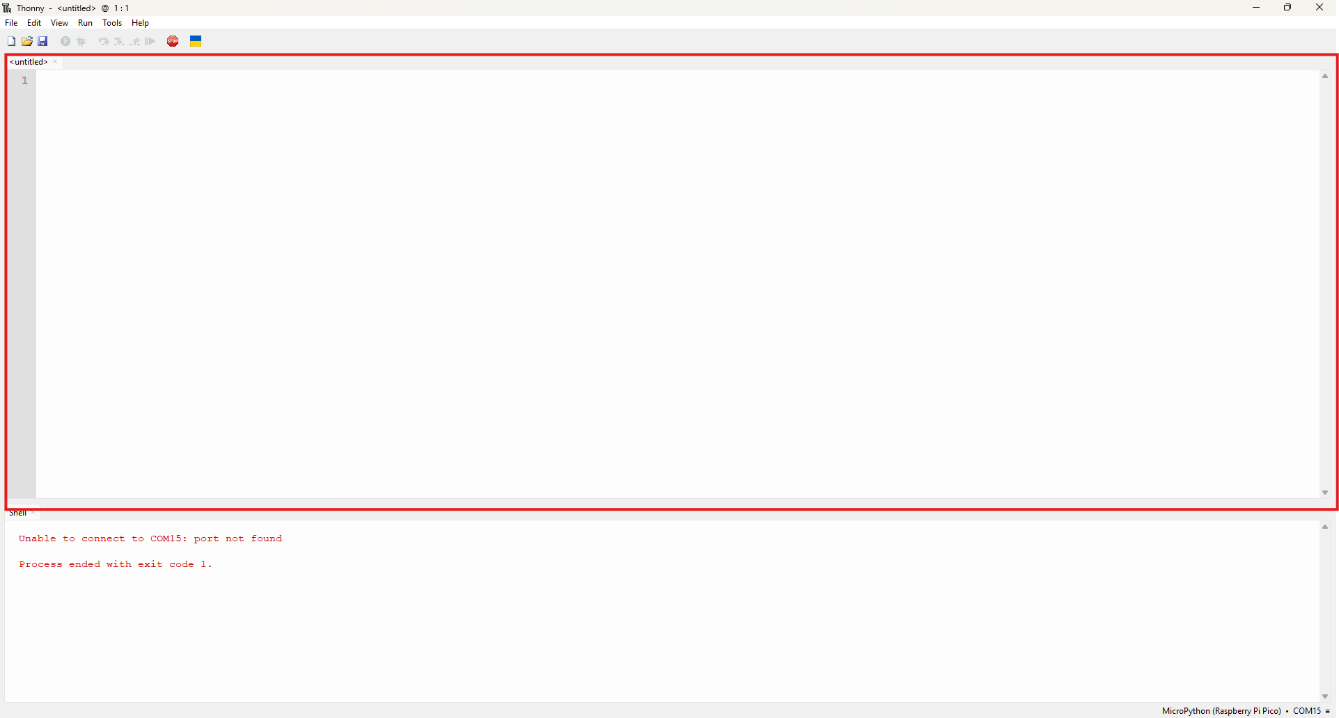
-
Paste the following MicroPython code into the script area
Get code here or paste the code below
  from machine import Pin, PWM
  import time

  # Motor Pins
  in1 = Pin(2, Pin.OUT)
  in2 = Pin(3, Pin.OUT)
  in3 = Pin(4, Pin.OUT)
  in4 = Pin(5, Pin.OUT)

  ena = PWM(Pin(6))
  enb = PWM(Pin(7))
  ena.freq(1000)
  enb.freq(1000)

  # Sensor Pins
  sensors = [Pin(i, Pin.IN) for i in range(8, 13)]

  # Speed Settings
  BASE_SPEED = 35000  # Slow and safe for normal movement
  MAX_SPEED = 40000   # Max PWM limit
  TURN_SPEED = 25000  # Slower speed for turning

  # PID Settings
  Kp = 8000  # Proportional gain, tune this as per your bot
  Ki = 0
  Kd = 0

  # PID Variables
  previous_error = 0
  integral = 0

  # Motor control functions
  def set_motor_speed(left_speed, right_speed):
      left_speed = max(0, min(MAX_SPEED, left_speed))
      right_speed = max(0, min(MAX_SPEED, right_speed))

      if left_speed == 0:
          in1.low()
          in2.low()
      else:
          in1.high()
          in2.low()

      if right_speed == 0:
          in3.low()
          in4.low()
      else:
          in3.high()
          in4.low()

      ena.duty_u16(left_speed)
      enb.duty_u16(right_speed)

  def stop():
      in1.low()
      in2.low()
      in3.low()
      in4.low()
      ena.duty_u16(0)
      enb.duty_u16(0)

  # Read sensor values
  def read_sensors():
      return [s.value() for s in sensors]

  # Calculate position (PID error calculation)
  def calculate_error(sensor_values):
      weights = [-2, -1, 0, 1, 2]
      total = 0
      count = 0
      for i in range(5):
          if sensor_values[i] == 0:  # Line detected (assuming black line)
              total += weights[i]
              count += 1
      if count == 0:
          return None  # Line lost
      return total / count

  # PID controller
  def pid_control(error):
      global previous_error, integral

      if error is None:
          return 0, 0  # No correction needed if line is lost

      integral += error
      derivative = error - previous_error
      correction = int(Kp * error + Ki * integral + Kd * derivative)

      previous_error = error

      return correction, correction

  # Smart Search with PID
  def smart_search():
      global previous_error, integral  # Reset PID variables for search
      previous_error = 0
      integral = 0

      for attempt in range(5):
          print("Search attempt", attempt+1)

          # Turn left (using PID control)
          in1.low()
          in2.high()
          in3.high()
          in4.low()
          ena.duty_u16(TURN_SPEED)
          enb.duty_u16(TURN_SPEED)
          time.sleep(0.5)
          stop()
          time.sleep(0.1)
          sensor_values = read_sensors()
          error = calculate_error(sensor_values)
          left_correction, right_correction = pid_control(error)

          if 0 in sensor_values:
              print("Found line after left turn")
              return

          # Turn right (using PID control)
          in1.high()
          in2.low()
          in3.low()
          in4.high()
          ena.duty_u16(TURN_SPEED)
          enb.duty_u16(TURN_SPEED)
          time.sleep(1.0)
          stop()
          time.sleep(0.1)
          sensor_values = read_sensors()
          error = calculate_error(sensor_values)
          left_correction, right_correction = pid_control(error)

          if 0 in sensor_values:
              print("Found line after right turn")
              return

      print("Failed to find line after searching.")

  # Main loop
  while True:
      sensor_values = read_sensors()
      print("Sensors:", sensor_values)

      error = calculate_error(sensor_values)

      if error is None:
          print("Line lost, starting search")
          stop()
          smart_search()
      else:
          correction = int(Kp * error)

          left_speed = BASE_SPEED - correction
          right_speed = BASE_SPEED + correction

          set_motor_speed(left_speed, right_speed)

      time.sleep(0.01)
Click on the save icon 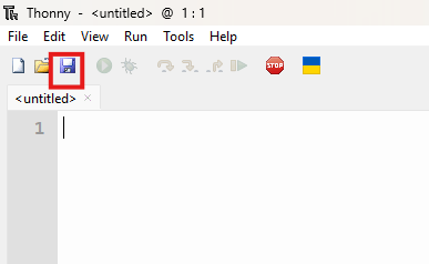
-
You will get a Prompt stating:-
Where do you want to save
1)Raspberry Pi Pico
2)To this PC
-
Choose Pico and save the file as
main.pyotherwise it will not auto-run on when powered on
The Hardware part
Connections
Here is a link for the line follower connections:- Click Here
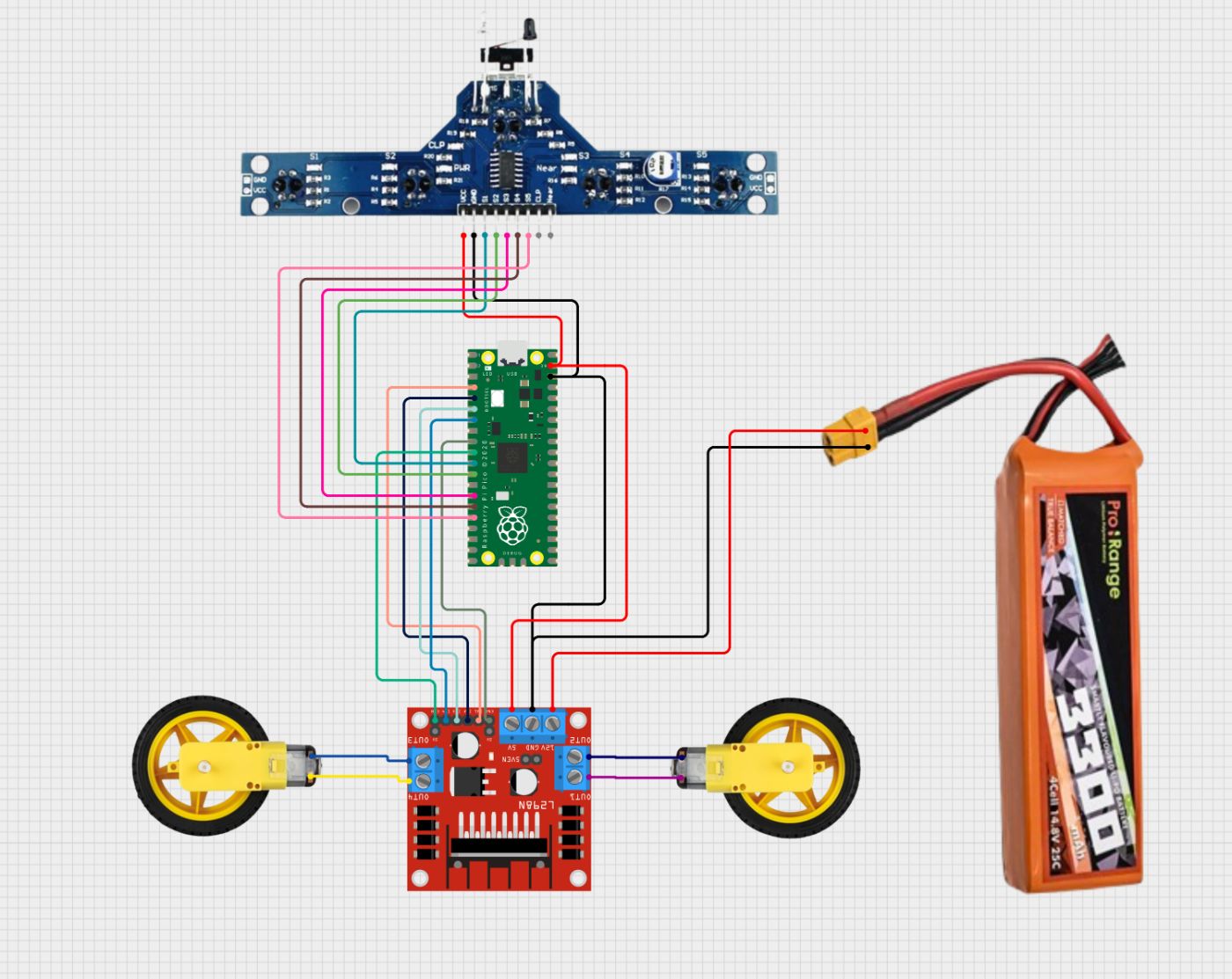
Connection Table
L298N to Pico
| L298N Pin | Connects To |
|—-|—-|
| IN1 | Pico GP2 |
| IN2 | Pico GP3 |
| IN3 | Pico GP4 |
| IN4 | Pico GP5 |
| ENA | Pico GP6 (PWM) |
| ENB | Pico GP7 (PWM) |
| VCC | 12V from the battery |
| GND | Pico GND & battery GND |
| 5V | V_Sys pin |
BFD 1000 to Pico
| IR Sensor Pin | Connects To (Pico Pin) | Function |
|—-|—-|—-|
| OUT1 | GP8 | Left-most sensor |
| OUT2 | GP9 | Left sensor |
| OUT3 | GP10 | Center sensor |
| OUT4 | GP11 | Right sensor |
| OUT5 | GP12 | Right-most sensor |
| VCC | 5V | Power |
| GND | GND | Ground |
IR Sensor Calibration
-
Run your line follower code in Thonny.
-
You should see values being printed in the following format corresponding to each sensor:-
Sensors: [x, x, x, x, x] -
Place the bot on a white surface. You should see:
[1, 1, 1, 1, 1](white reflects IR = HIGH). -
Move the centre sensor over the black line. You should see:
[1, 1, 0, 1, 1](black absorbs IR = LOW). -
Slide the bot side to side across the line. All sensors should detect black (
0) when over a line. -
Adjust potentiometers (if needed) on the IR sensor for reliable
0/1switching.
Test Run Video
Drive Link:-https://drive.google.com/file/d/1ODuU0T4gvLMk8YIl7x5UDorZBtHX7OeK/view?usp=sharing
That’s all, folks, for this project
Meet you in another tutorial like this
Thanks,
Shivank Dan