The Relentless Test of Time and Environment
The camera-engineering lifecycle comprises several connected stages. Article 1: Component Selection defines the system’s theoretical upper limits through component selection; Article 2: Lab Build-up & Management establishes a high-precision laboratory measurement system; Article 3: Intrinsic & Extrinsic Calibration provides accurate spatial awareness for edge AI through geometric calibration; and Article 4: Factory Testing & AA establishes consistency in the initial quality of cameras leaving the factory.
However, when a camera leaves the factory and is installed in a commercial vehicle, the real test has just begun. In-cabin equipment may experience a wide temperature range under summer solar exposure and winter cold; the actual upper and lower limits depend on vehicle type, installation position, shading conditions, and product requirements. This article uses −40°C to +85°C as an illustrative validation range. In addition, powertrain and road inputs create continuous vibration and shock, while car-wash water, humidity, and road salt can challenge housing and sealing structures.
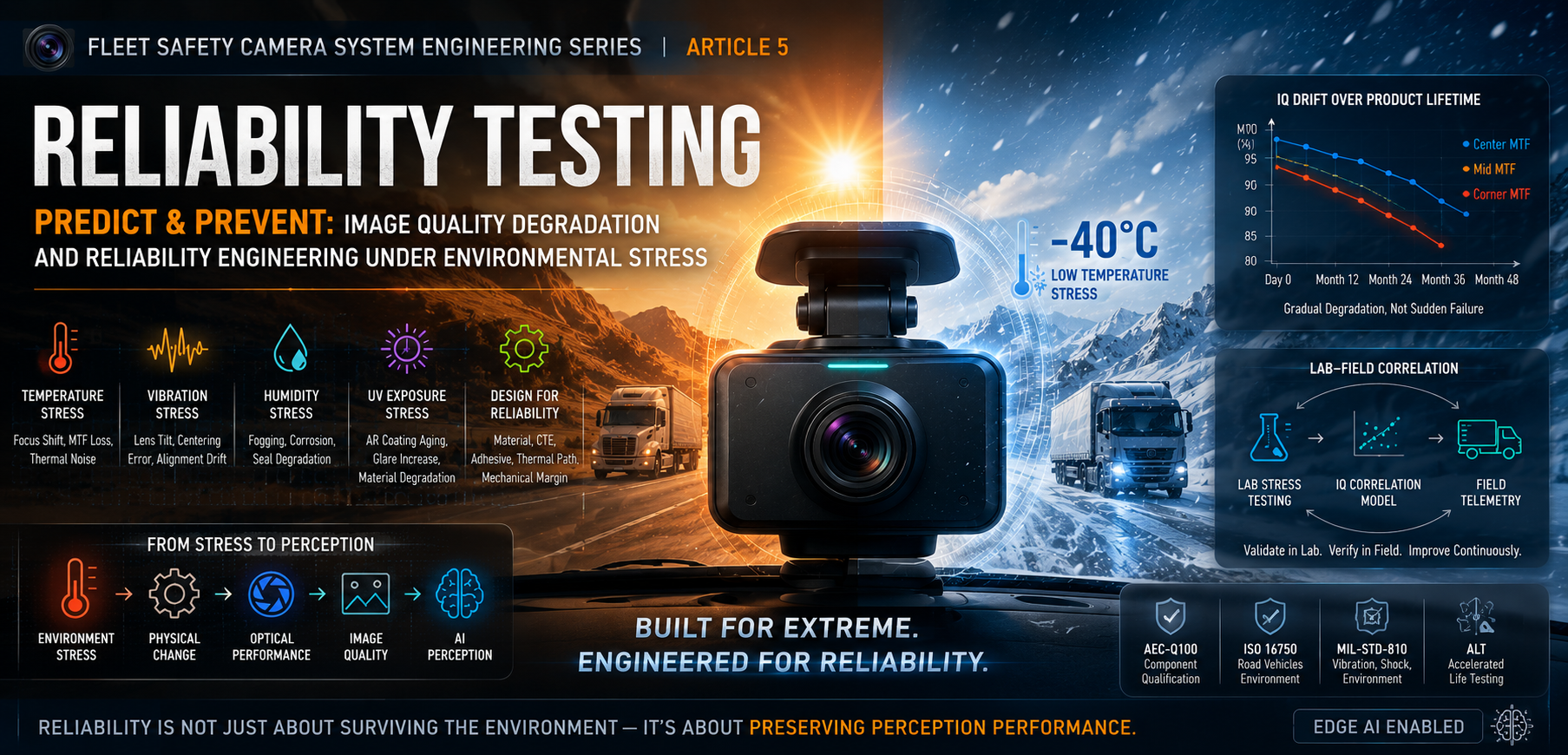
Under the long-term effects of these environmental stresses, cameras that performed well in factory tests may gradually exhibit focus shift, Modulation Transfer Function (MTF) degradation, optical-axis deviation, and even structural failure. For edge AI systems highly dependent on precise image input, this gradual degradation of image quality (IQ Drift) can be harder to detect and more consequential than sudden hardware damage (Hard Failure). In actual fleet operations, reliability issues may not always appear as abrupt hardware failures; many camera systems can instead experience a prolonged period of performance drift. For example, a Normalized MTF Index may be defined as 100 on Day 0, decline to 95 at Month 12, and further decline to 90 at Month 36. The AI model may still be operating, while detection accuracy and the handling of edge cases may have declined.

The core value of Reliability Testing lies in compressing the tests of time and environment into the laboratory phase. It is not merely about obtaining a certificate of compliance, but rather deeply understanding how physical stress leads to long-term degradation of image quality, thereby establishing preventive mechanisms during the design phase. This article will explore the destructive mechanisms of environmental stress on image quality, analyze the strategies of Accelerated Life Testing, and provide engineering perspectives on the reliability challenges of modern multi-camera systems.
Scope Boundary: This article focuses on environmental-reliability mechanisms that affect image quality (IQ) and downstream perception. Power integrity, EMC/ESD, cybersecurity, connectivity, and other reliability domains in which IQ is not the primary impact pathway are outside its scope.
1: Environmental Stress and Image Quality Degradation Mechanisms
To predict and prevent failures, engineers must first understand how environmental stress interacts with the physical structure of the camera. In fleet safety cameras, the primary stress domains can be categorized as temperature stress, mechanical stress, and environmental corrosion.
1.1 Establishing the Systems Thinking of Reliability Budget
Before delving into various stresses, a core concept must be established: the Reliability Budget. Just as Article 3: Intrinsic & Extrinsic Calibration uses a Geometry Budget to allocate calibration errors, reliability engineering likewise translates environmental stress into a quantifiable chain of impact:
Environmental Stress → Physical Change → Optical Performance → Image Quality → AI Perception
For example, regarding temperature stress, this chain unfolds specifically as:
Temperature Rise (illustrative condition) → Lens Expansion → Focus Shift → MTF Loss → Detection Accuracy Drop
By establishing a Reliability Budget, reliability validation no longer simply pursues “passing environmental tests.” Instead, it analyzes and quantifies the potential effect of each physical variable on final AI perception performance. This enables engineering teams to strategically allocate tolerance budgets to optical structures, sensors, and edge AI algorithms during the design phase.
Geometry Budget controls spatial accuracy on Day 0, while Reliability Budget preserves that accuracy throughout the product lifetime.

1.2 Temperature Stress: Thermal Expansion, Focus Shift, and Thermal Noise
Temperature is one of the environmental variables that most influence a camera’s optical performance. Fleet cameras may use Glass-Plastic Hybrid Lenses to balance a wide field of view with wide-temperature operating conditions. However, the Coefficient of Thermal Expansion (CTE) of plastic lenses is much greater than that of glass, which means that under extreme high and low temperatures, the curvature of the lenses themselves and the spacing between lenses will change significantly.
The most direct consequence of this physical deformation is Focus Shift. When a camera operates at elevated temperatures, the focal point may deviate from the sensor plane, causing sharp images to become blurred and degrading the overall Modulation Transfer Function (MTF). To mitigate this issue, athermalized lens designs use the offsetting thermal-expansion characteristics of lenses made from different materials to keep focus shift within the allowable depth of field. Where product requirements call for a wide high- and low-temperature operating range while maintaining high-resolution output, the optical system requires sufficient athermalized design and temperature tolerance to preserve stable imaging under both solar loading and severe cold.
In addition to the optical structure, temperature also has a significant effect on the sensor’s electrical performance. As temperature rises, sensor Dark Current generally increases, with its magnitude depending on sensor architecture and process technology; it can in turn raise Thermal Noise. In nighttime or low-light environments, this can degrade the image Signal-to-Noise Ratio (SNR) and reduce the performance of AI models that rely on low-light features, such as driver-fatigue monitoring.
1.3 Mechanical Stress: Broadband Vibration, Structural Resonance, and Adhesive Creep
During operation, commercial vehicles generate compound mechanical excitation driven by the powertrain, road input, vehicle body, and mounting structure, including broadband vibration, structural resonances, and transient shocks. These mechanical stresses are transmitted to the interior of the camera module through the vehicle body and mounting brackets.
Article 4: Factory Testing & AA describes Active Alignment (AA), which uses UV adhesive to secure the lens at a target focal position. Under the combined effects of long-term vibration and thermal cycling, however, the cured adhesive may experience microscopic Adhesive Creep or develop micro-cracks. Because commercial-fleet vibration environments are severe, engineering teams commonly use applicable vehicle or environmental-vibration specifications to verify that a system can preserve optical stability throughout its intended service life under the combined effects of broadband vehicle vibration, structural resonances, and transient road shocks.
This small mechanical deformation can cause lens tilt or decentering relative to the sensor plane. In ultra-wide-angle or high-resolution systems, even a small lens tilt or decentering error can reduce corner MTF and invalidate a previously calibrated geometric-distortion model. This not only affects visual quality but also causes edge AI to produce spatial positioning errors when performing Lane Departure Warning (LDW) or Forward Collision Warning (FCW).
1.4 Environmental Corrosion: Humidity, Salt Spray, and UV Exposure
Auxiliary cameras mounted outside the vehicle (such as side or rear blind-spot cameras) face even harsher environmental challenges. Moisture penetration can create internal electrical risks and can also form hard-to-clear fogging on the inside of the lens, significantly obstructing light transmission.
On roads cleared of snow in winter, salt-rich spray causes intense chemical corrosion on the camera housing and lens seams. Furthermore, long-term Ultraviolet (UV) exposure leads to embrittlement of the plastic housing materials and may cause long-term degradation of the Anti-Reflective (AR) Coating on the lens surface, increasing the probability of Glare and Ghosting.
Rapid temperature transitions can also create optical risks that differ from those of steady high-temperature, high-humidity exposure. When a cold camera rapidly enters a warm and humid environment, internal optical surfaces may fall below the dew point of the surrounding air, creating transient or persistent internal condensation. The resulting fogging and optical scatter can reduce contrast, increase glare, and temporarily or permanently degrade MTF; thermal-shock and dew-point-crossing conditions should therefore be assessed as part of sealing and optical-reliability validation.

2: Reliability Validation and Accelerated Life Testing
Having understood the destruction mechanisms, the next step is to establish a scientific validation strategy. Reliability validation for fleet cameras generally draws on automotive-electronics and road-vehicle environmental practices. Semiconductor components such as SoCs and sensor-interface ICs may reference component-level qualification standards such as AEC-Q100, whereas environmental reliability for the complete camera or module should be defined according to product architecture and vehicle-use conditions, with appropriate consideration of road-vehicle environment, vibration, temperature–humidity, corrosion, and protection requirements.
2.1 Reliability Validation Flow: A Continuous Engineering Loop
Reliability validation should not be treated as a final qualification review before design freeze. It is a continuous engineering loop spanning requirement definition, measurable baselines, controlled stress, drift quantification, and design feedback. This loop extends the measurement capability established in Article 2: Lab Build-up & Management and the production consistency pursued in Article 4: Factory Testing & AA into verifiable reliability objectives across the product lifecycle.

The flow should start with drift limits defined by the Reliability Budget, establish a controlled IQ Lab baseline, apply traceable thermal, vibration, and humidity stresses, and quantify IQ Drift from before-and-after measurements. Laboratory predictions must then be verified against field-use evidence and fed back into material selection, structural design, thermal design, calibration strategy, and subsequent validation plans. The value of reliability validation is that each test iteration increases the confidence of the next design decision.
Reliability validation is a continuous engineering loop rather than a final qualification activity.
2.2 Reliability Test Matrix: Aligning Tests with Imaging Risk
A reliability plan should not be a list organized around test names. It should be a decision matrix that aligns each environmental stress, potential failure mechanism, and measurable IQ metric. This prevents the gap in which a test is complete but the drift that truly affects perception performance has not been measured.

The purpose of this matrix is not to replace detailed test specifications. It enables camera-system engineers to answer early in validation planning: which image-quality attribute and AI perception capability is each stress test intended to protect? Each reliability test should also have predefined entry criteria, stress-exposure conditions, measurement checkpoints, and exit criteria linked to the allocated IQ drift limits.
2.3 Accelerated Life Testing (ALT)
The target service life of fleet cameras is commonly measured in years. Because validating durability on the real-time scale may not fit the development cycle, Accelerated Life Testing (ALT) can be an important tool for shortening reliability validation cycles when the underlying failure mechanisms and acceleration models are sufficiently understood.
The purpose of ALT is not simply to make the environment more extreme. It is to accelerate degradation while confirming that the underlying failure mechanism remains unchanged. For thermally activated mechanisms, an appropriate model such as Arrhenius may be used; temperature–humidity and mechanical-fatigue mechanisms require their respective acceleration models. Only when the failure mechanism, stress conditions, and model assumptions are valid can engineers reasonably estimate field-life behavior or degradation rate.
For example, high-temperature/high-humidity conditions can accelerate moisture uptake, corrosion, and package degradation. However, the acceleration factor must be established from the failure mechanism, material properties, and validation model; test duration must not be equated directly with a specific number of field-service years. For camera systems, the suitability of 85°C/85% relative humidity (85/85) also depends on the sealing architecture, materials, adhesive, sensor package, PCB, vent membrane, and condensation mechanisms.

2.4 Design for Reliability: From Passive Validation to Active Prevention
Before executing ALT, an essential step is Design for Reliability. Reliability validation should confirm whether a system was engineered to resist environmental stress from the outset; preventive mechanisms should therefore be incorporated during the hardware-design phase:
- Material Selection & CTE Matching: Materials for the lens barrel and sensor substrate should have compatible Coefficients of Thermal Expansion (CTE) to reduce relative displacement caused by thermal cycling.
- Adhesive Selection: The UV adhesive used in the AA process not only needs rapid curing but also requires a high Glass Transition Temperature (Tg) and an appropriate elastic modulus to absorb vibration stress without creeping.
- Thermal Path: Design independent and efficient thermal dissipation channels for high-power SoCs and image sensors to prevent local hotspots from affecting the stability of the optical structure. As new-generation fleet cameras execute multiple vision AI models concurrently on-device, thermal dissipation from their compute platforms increases significantly. The thermal design must therefore ensure that heat from the SoC does not conduct to adjacent optical lens modules and induce focus shift.
- Mechanical Margin: Retain sufficient tolerance margins in the structural design to ensure that even under the worst-case vibration scenarios, lens components do not collide with the housing.

From Failure Mode to Design Countermeasure
Design reviews should connect each anticipated failure mode directly to an actionable structural, material, or thermal countermeasure. This ensures that reliability testing not only reveals weaknesses, but also verifies whether the countermeasure meaningfully reduces drift risk.

2.5 Establishing the Quantitative Correlation between Stress and Image Quality
Traditional reliability testing often focuses only on whether the product “can turn on” or whether a “Hard Failure” has occurred. However, as mentioned in the introduction, the real challenge facing fleet cameras is gradual IQ Drift. For imaging systems, a black-and-white judgment standard is insufficient.
A rigorous IQ reliability testing process must closely integrate stress testing with the high-precision laboratory measurements established in Article 2: Lab Build-up & Management. Before, during, and after high-temperature storage, Thermal Cycling, or vibration tests, engineers should return the camera to the IQ Lab to remeasure MTF, SFR, distortion coefficients, and color reproduction. Pre- and post-stress measurements should also distinguish true hardware or opto-mechanical drift from differences introduced by recalibration, avoiding the misclassification of calibration error as reliability degradation.
By tracking the trajectory of these key IQ metrics as stress accumulates, engineers can build quantitative degradation models and define acceptable “degradation tolerances.” MTBF should not be used as the sole metric; Reliability KPIs based on image quality should be established in parallel. The values below are engineering examples intended to illustrate KPI-design methods; actual tolerances should be established from product requirements, optical design, AI tasks, and validation data. For example, a system might define the following KPIs after a specified thermal-cycling condition:
- Best-Focus Position Drift: < 5 μm
- Center MTF Loss: < 10%
- Corner MTF Loss: < 15%
- Relative Extrinsic Rotation Drift: < 0.1°
- Color Shift: ΔE < 3
This quantitative correlation analysis and KPI tracking are important for assessing whether edge AI algorithms can maintain stable operation toward the end of the product lifecycle.
Statistical Confidence and Sample Strategy
Reliability conclusions should also account for sample size, confidence level, and failure-censoring conditions. A small number of engineering samples may be useful for mechanism discovery, but production-representative validation should use an appropriate sample strategy to establish statistical confidence in the observed IQ drift and failure rates. The required sample size and confidence level should be determined from the target reliability, expected failure rate, test duration, and available field data; a small number of samples all passing does not by itself demonstrate reliability across the full service life.
AI Performance Drift: Cumulative Loss of Perception Margin
The relationship between IQ Drift and AI performance is not a fixed one-to-one linear mapping. While image quality remains within an apparently acceptable range, average model accuracy may seem stable. However, as MTF, SNR, geometric consistency, and color stability progressively consume input margin, detection robustness in edge cases usually declines first. This is why fleet-camera reliability risk often appears as a system that remains active while false positives, missed detections, or cross-camera tracking failures increase, rather than as a sudden loss of output.

Reliability KPIs should therefore not be expressed only as pass or fail. They should also preserve adequate AI perception margin and observe post-drift performance in representative scenarios and difficult samples. This principle connects the Reliability Budget at component and opto-mechanical levels to the perception risk the system ultimately needs to control.
2.6 Laboratory–Field Reliability Correlation
Laboratory tests shorten the time needed to observe failure modes, but they cannot replace validation in real fleet environments. Road type, vehicle platform, installation position, seasonal climate, and usage behavior all change the actual stress spectrum. The next step in reliability engineering is therefore not merely confirming that samples pass qualification thresholds, but determining whether laboratory drift trends can predict field degradation trends.

In practice, engineering teams should compare laboratory degradation curves with the IQ-metric trends observed through fleet telemetry and examine whether their slopes, inflection points, and failure modes are consistent. Field degradation that occurs earlier than laboratory predictions may indicate that stress spectra, assembly variation, or usage conditions have not been sufficiently represented. Conversely, excessively conservative laboratory results can motivate recalibration of acceleration factors and test conditions. This section establishes only the correlation principle between reliability models and field data; the data architecture and closed-loop optimization methodology for fleet telemetry will be examined in Article 6: Customer Telemetry & Closed-loop Optimization.
Laboratory reliability tests should predict field degradation trends rather than merely passing qualification criteria.
3: Reliability Challenges of Multi-Camera Systems
Fleet safety camera systems may employ multi-camera architectures. Common configurations combine a high-resolution forward-facing camera, a driver-monitoring camera, and auxiliary cameras for wide-angle coverage or specific perception tasks. Such architectures can support forward safety perception, driver-behavior analysis, and cross-camera object tracking, but also introduce new reliability challenges in thermal management, mechanical retention, and geometric stability.
3.1 System-Level Thermal Management and Local Hotspots
In a multi-camera system, in addition to the main SoC, there are multiple image sensors, ISPs, and Infrared (IR) LED modules used for night vision. These high-power components are typically encapsulated in a compact housing, resulting in highly uneven heat distribution within the system.
Cameras with low-light driver-monitoring functionality may use Infrared (IR) LEDs. Continuous nighttime operation can generate appreciable heat. If thermal management is not designed properly, this heat may conduct to adjacent forward-facing camera modules, causing localized focus shift or increased sensor noise. Therefore, the reliability design of multi-camera systems must employ system-level Thermal Simulation and use Thermal Pads, Heat Spreaders, Metal Heat Sinks, or other appropriate thermal-management structures to route heat effectively to the housing for dissipation.

3.2 Long-Term Stability of Geometric Relationships
In multi-camera systems capable of 360° stitching or stereo depth perception, the relative spatial positions (i.e., relative extrinsic matrices) between cameras must remain within the allocated geometry tolerance.
As described in Article 3: Intrinsic & Extrinsic Calibration, small geometric errors can be amplified in spatial projection. Under long-term vehicle vibration and thermal expansion/contraction, brackets that retain multiple cameras may undergo minute deformation. Even a small relative-angle drift can create geometric inconsistency in overlapping fields of view for wide-angle, multi-camera stitching, or cross-camera tracking; the actual tolerance depends on FOV, camera spacing, overlap region, and algorithm design.
To reduce this risk, the hardware design can use high-stiffness bracket materials and traceable geometric-tolerance management. In multi-camera systems that support it, structural reinforcement may be supplemented by software-level online dynamic calibration or drift-monitoring mechanisms to detect and compensate for long-term extrinsic changes. The appropriate approach should be determined by system architecture, observable features, and service strategy.
Conclusion: A Systemic Defense Where Prevention is Better Than Cure
Reliability testing is not an isolated checkpoint in the product development process, but a critical defense line running through the entire systems engineering. By understanding the degradation mechanisms of environmental stress on image quality and combining Accelerated Life Testing with high-precision IQ measurements, engineers can identify and mitigate potential failure modes during the design phase.
When a camera system maintains its optical and geometric characteristics within specified environmental conditions, it protects the perceptual foundation of downstream edge AI algorithms. However, even after rigorous laboratory reliability validation, real-world complexity may still introduce unanticipated challenges.
The objective of reliability engineering is not merely to survive environmental stress, but to preserve stable perception performance throughout the entire product lifecycle.
The next article (Article 6: Customer Telemetry & Closed-loop Optimization) will examine how IQ Drift can be monitored through field telemetry after camera systems are deployed at fleet scale, and how a closed-loop optimization mechanism can drive hardware iteration and software updates.